Friday, June 30, 2006

1994 3.0L Dodge Caravan dash gauges not working!

Car wiring question:

I am a new ATS member and my gauges on my van quit working 2 days ago. When it happened, the windshield wipers will not work in the delay mode and won’t park. After reading your lessons, I checked the instrument panel power source and ground supplies and all their readings are within limits. I use this van for my business and I am really scared that if this is not fix right away, I might get into accident. (Bringing the van to a garage is out of question). Can you help?

Vehicle wiring advice:

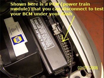
Every time your gauges go on this vehicle, the problem is usually the BCM or body control module. It controls all the rest of your vehicle functions except engine performance, which is controlled by engine control module (ecm). Start by disconnecting your battery for at least 10 minutes to reset the bcm. Sometimes the bcm locks up and if you disconnect the battery, the bcm will unlock itself.

If resetting the bcm does not correct the problem, try these:

Tap the bcm and see if the gauge lights come on. Open it up and see if you can see inside for signs of heat burns, corrosion and moisture. Check the ground connector to the bcm for looseness.

Notes:

Bcm is located under the dash and right of the steering column. Disconnect the battery every time you service the bcm. Never replace your bcm with a used one. Every bcm is unique only to every vehicle and they are not interchangeable.

What ever you do when working under the dash panel, do not touch the yellow-taped wiring harness to avoid accidental deployment of the air bag which will activate even with the battery disconnected. Remember: you do this service at your own risk.

Thursday, June 29, 2006

1998 Dodge Caravan 3.3L with gas, tach, odometer and temp gauges not working.


Car wiring question:

This minivan was working well all the time when suddenly all my gauges quit on me. I tried disconnecting the battery for 5 minutes to reset the body control module but that did not work. I also tried wiggling the grounds I could find it in the engine compartment and the left kick panel and they are secure which does not show corrosion. All fuses are OK and I am out of wits here. Do you have any suggestions?

Vehicle wiring advice:

You are in the right track in checking the BCM but make sure the plug in terminals to the body control module (BCM) is tight and clean. You might have to remove them and physically check the pins for looseness. It has been reported by other members that this would cause the problem. Try also to unplug the ABS, Airbag, HVAC, PCM, TCM modules etc and if while unplugging these the gauges come back, you just found your problem.

I have also described in my previous solutions in testing the bcm BUS wires. You should check the voltages in the bus connectors link located at the left side of the dash panel. You can activate the bus voltages by opening doors and trunks. You should get a reading of around 2.5 volts on each wire. A garage shop can also verify for you if there is a square wave across those 2 bus wires. The BCM is over $300 and scanning for square wave would be a good investment.

Finally, check the dash panel circuit board for wiring terminal connections. It could be loose or the grounds are not secure.

Notes:

It is preferable if you have a wiring diagram so you can see the various ground and supply connections including all the modules connected to the BCM. Should you have any difficulty, ats can described to you all the wires involved.

Whenever working under the dash panel, do not touch the yellow-taped wiring harness to avoid accidental deployment of the air bag which will activate even with the battery disconnected. Remember: you do this service at your own risk.

Disconnect battery negative terminal everytime you work any electrical component.

Wednesday, June 28, 2006

1993 2.5L Dodge Dynasty alternator over charging


Car wiring question:

I just subscribed to your program and the reason I need your service is my alternator problem. I have a 1993 2.5L Dodge Dynasty that is giving me fits! It had an alternator code for overcharging code and an engine code because the engine light is on. I can verify that it is overcharging because my battery is boiling. I changed the alternator because I thought that would fix the problem but to my surprise it is still the same! Now I am not sure if the rebuilt alternator I got is bad or I have a different problem in my hand. Please help.

Vehicle wiring advice:
Contrary to a lot of designs, your alternator’s voltage regulator does not reside in the alternator housing itself. Regulation comes from the your pcm (computer) which also control alternator field control. In your alternator, you will see these wires:

Black gray wire is from your fuse box Black wire is from your battery negative terminal Dark green orange wire is the field voltage wire from your computer (pcm) Dark green wire is your voltage regulation wire also from pcm.

Once there is a failure, the pcm will communicate with you by flashing the “check engine” light to warn you of the problem. In this case before condemning the alternator, you have to check the dark green wire from the pcm. To do this, go to your pcm terminal pin 20 and measure the resistance between the pin 20 terminal against the ground. Do this with your key turn off. If the resistance is less than 5 ohms, that wire is shorted to ground indicating a pcm failure.

Notes:

The pcm is located at the left front corner of engine compartment.

Whenever you touch the alternator or the pcm, disconnect the battery negative terminal to prevent damages to the components.

Reset your pcm after the each repairs and go for a road test before getting the code again. If the problem is fixed, the “check engine” lights will disappear.

What ever you do when working under the dash panel, do not touch the yellow-taped wiring harness to avoid accidental deployment of the air bag which will activate even with the battery disconnected. Remember: you do this service at your own risk.

Tuesday, June 27, 2006

1995 Honda Civic 1.6L has no spark


Car wiring question:

My 1995 Honda Civic has no spark when tested with ST125 tester. I wonder if the main relay would cause the problem since my NOID light tester blinked when I tested the injectors? How do I test if the main relay is good? There is also a presence of oil in my distributor and I wonder if my distributor igniter or coil is the culprit? Your help will be appreciated.

Vehicle wiring advice:


The Honda main relay is use to power up your coil and ecm but the quickest way to test that is to listen to your fuel pump if you can hear it come on when you turn your key to the on position. The main relay does it thru the yellow black wire that powers the injector and the green yellow wire that goes to pin #7 at your computer. However, the quickest way to check if the main relay is working is to watch the dash “engine service” light. It should come on when you turn the key on and quit. If it stays on, either the main relay or ecu (computer) is bad and you can find that if you have a code.

The coil can be checked quickly by removing the cap of the distributor and checking the negative side of the coil with a test light. If you crank it and the test light blinks, it means the module called igniter is working and the coil is bad. Make sure you have 12 volts going to the coil on the positive side with key on.

The presence of oil in your distributor will usually make the sensors inside the distributor fail and the most common symptom of that is there will be no injector signal which points to a bad crank sensor or cam sensor. When this happens, replace the sensors too or the complete distributor.

Note:

It is a common practice among garages to change BOTH coil and igniter when either one of them fails. Bad spark plugs usually makes the coil go bad and make sure to change them when servicing the distributor including plug wires, cap and rotors. Always buy OEM parts if you can to avoid repeated failures.

Disconnect battery negative terminal everytime you work any electrical component.

Monday, June 26, 2006

1994 Ford Explorer 4.0L engine with no start and no computer communication

I have this 1994 Ford Explorer that is driving me nuts! Whenever it is cold
out there, it won’t start. If I leave the key on for a few minutes, it would
start. This never happened after it has started during the day but only in
the morning when it is parked overnight. Funny thing too is when this happens;
the “service engine” light won’t come on. After I left the key on for sometime,
the light comes on and it will start. I got no spark and no fuel that leads me
to change the engine computer but the problem is still there. Please help!

Vehicle wiring advice:

If your “check engine” light is not coming on during this problem, I agree with
you in suspecting it is a computer problem but testing for spark and fuel is
not enough. The computer will not work sometimes because there are problems in
other parts of the electronic system. Begin this by accessing your ground
supplies at the computer terminals. With your ignition key on, see if you get
0.250 volt or higher on any of the ground pins which will indicate a short.

Another factor is to look at your VREF signal pin at the computer terminal. With
key on, you should get 5 volts. If not, one of the output solenoids or sensors
is defective. You can test this by unplugging them one at a time until the VREF
voltage becomes 5 volts. The last component that you unplug is the culprit.

Notes:

It is preferable if you use a wiring diagram to trace these computer pins but
in case you don’t have it, ats can described the wire colors for you.

Disconnect battery negative terminal everytime you work on any electrical component.

What ever you do when working under the dash panel, do not touch the yellow-taped
wiring harness to avoid accidental deployment of the air bag which will activate
even with the battery disconnected. Remember: you do this service at your own risk.

Sunday, June 25, 2006

1988 GM truck with 5.7L engine computer fuse keeps blowing.

Car wiring question:

I have a 1988 GM truck with 5.7 Liter engine. I bought it used 3 years ago and I took care of it and had no problem until today. The engine won’t start and when I looked at the fuse box, the ECM fuse keeps blowing. I checked for shorts and drain using my wiring diagram but I cannot find anything wrong. Do you have any suggestions?

Vehicle wiring advice:

Looking at the wiring diagram of this engine, your ECM supplies both power (12 volts) and ground to the whole system. To isolate the ECM, unplug it and see if the ECM fuse blows again. If it does, the problem is in the wires and loads of the ECM like injectors, solenoids, alternator, fuel pump, relays, etc. You can then unplug them one at a time until the blowing of the fuse stops. The last component you touched is the probable culprit including its circuit. However, if the ECM fuse does not blow when disconnected shows that the ECM itself is the problem.

Notes:

ECM is located behind the right side of dash usually at the back of the glove box. Always disconnect the battery negative terminal when working on the ECM.

The ECM grounds the 8 injectors of this engine in order to work. Looking at your wiring diagram, power to the injectors comes to the black wire, which comes from a fuse box. However the ground comes from the black light green and black pink wires. Both of these wires come direct from the ECM. If one of the injectors is shorted, it will blow also the ECM fuse to protect itself.

What ever you do when working under the dash panel, do not touch the yellow-taped wiring harness to avoid accidental deployment of the air bag which will activate even with the battery disconnected. Remember: you do this service at your own risk.

Friday, June 23, 2006

Wiring Diagram Symbols

Wiring diagrams usually comes with symbols, which depict all the components used in the wiring diagram of your vehicle. Being a do it yourself auto repair person or just a regular person, can you recognized the basic electrical wiring diagram symbols?

Shown below are the most common typical electrical symbols used in automotive wiring diagrams. As your basic wiring diagrams symbols, feel free to familiarize yourself with these symbols until you get used to it when you see it in a wiring diagram. Using the electrical wiring color codings plus these wiring symbols should help you locate the component you are looking for.

To see some basic wiring symbols, please click HERE

(then click view in your toolbar and click full screen to zoom in)

NOTE:

After you bought yourself a wiring diagram and you have difficulty in using it, contact ATS if you are a subscriber and our technician will help you trace the wires.

The above wiring diagram symbols lists are just a partial list. Most modern vehicle made nowadays will have more of these electrical wiring diagram symbols. You can get a complete list by availing yourself of a complete wiring diagram book for your specific vehicle as recommended by the links below.


Thursday, June 22, 2006

Wiring diagram wire color abbreviations

To trace wiring diagrams, vehicle manufacturers designed the wires so that you can
identify it using its wire colors. This color acts as a code so you can easily
follow its origin and path.

In reading wiring diagrams, if you know the color of the wire, you can trace the
component associated with it and the rest of the circuits that is working with
that component.

To help you in reading the wire color codes, every automotive wiring diagram has
its own color-coding abbreviations to make it easy for you. Here is the wiring color
abbreviations use on most domestic and imported cars:

COLOR..........common code........... Aternative code

Black...............Blk............................Bk
Blue................Blu............................Bu
Brown.............Brn............................Bn
Dark Blue.........DrBlu.........................DkBu
Dark Green.......DrGrn.......................DkGn
Green..............Grn.........................Gn
Gray...............Gry..........................Gy
Light Blue.........Lt Blu.......................Lt Bu
Light Green......Lt Green.....................Lt Gn
Orange...........Org..........................Og
Pink................Pnk..........................Pk
Purple.............Ppl..........................Pl
Red................Red..........................Red
Tan................Tan..........................Tan
Violet.............Vio...........................Vi
White............Wht...........................Wt
Yellow...........Yel.............................Yl

NOTE:

Most cars uses BLACK wire as ground wire and RED wire as power supply wire. This is
especially true with domestic cars but it is different with imported cars. To get a
complete set of wiring codes, avail yourself a wiring manual for your specific vehicle.

Wednesday, June 21, 2006

How to trace and read your wiring diagram

To use any wiring diagram for your vehicle, you must be able to identify the components and types of system being used so that you will know if such automotive electrical diagram will work for you.

Tracing wiring diagram requires understanding the source of power and ground supplies including the ability to read color coding abbreviations for the wires and components. This, coupled with knowing the function of each component, will teach you how to trace the path of both power and ground supply. Once you grasp this, you should be able to read any wiring diagrams.

Most automotive wiring diagrams depict the power source usually on the top of the wiring diagram and the ground source at the bottom. The wires connect any components in between, which uses color coding. This coding makes tracing easy when testing different components at the same time. In the older times, wiring diagrams can be put in fewer pages of a book, which makes tracing very easy. Nowadays, because of the complex system being used, wiring diagrams are made to show individual system so they can be analyzed separately.

When tracing different system, you need to recognize the different circuit being used in your engine. This why wiring diagrams are composed of sub system of circuits working as a whole. Here are some typical electrical system (or circuits) used in a typical single modern day car:

# Alarm control circuit
# ABS circuit
# AC (and compressor) circuit
# Airbag circuit
# Charging (alternator) circuit

# Engine control (computer) circuit
# Heater (and blower) circuit
# Horn circuit
# Instrument panel circuit
# Lighting (both external and internal) circuit
# Ignition (distributor or non-distributor) circuit

# Power window circuit
# Power door (and trunk) circuit
# Radio and audio circuit
# Starting and Charging circuit
# Transmission (both automatic and manual) circuit
# Washer and wiper control circuit

When you look at this as a whole, it is very intimidating to fix any system when you consider the numerous circuits involved but if you attack it with one circuit at a time and use a wiring diagram, you should be able to handle it. So remember when you have any vehicle electrical wiring problem: find out first what symptoms is showing the system being used and then use the system wiring diagram to trace the fault. Example: you cannot fix your starting problem by checking your AC system. Only thru proper understanding of what system is actually at play that you will be able to trace it.

Sunday, June 18, 2006

Cheap tools for testing wiring diagrams

When tracing automotive wiring diagrams, it is not required to use expensive tools to solve your wiring problems. If you have the cheap tools that ATS recommends and there is a parts store near you, you should be able to check most of your wiring problems.

Most modern day garages update their equipment every year for one reason: to fix more vehicles at record time, which can result to more profit. However, there is no need for you to do this if you are only looking after the family’s vehicles. If you have these tools that I recommend below, you should be able to handle most of your vehicle problems. Remember too, as you get to work on your vehicle often, you will get familiar with it and you will be the first to know if there is a problem especially if you drive it everyday or you do the regular car maintenance

Here are the some electrical tools I would recommend for a handy man:

  • 4 feet long jumper wire (usually gage 16) with alligator clips
  • Soldering gun and solder kit
  • *A digital voltmeter that can read under 1 volt.
  • A set of inexpensive pliers for cutting and connecting wires.
  • 12 volts test light tester
  • **A set of pins about 1 inch long for piercing wires.
  • ***A box of electrical connectors for different sizes of wires

    NOTES:

    * With low impedance to prevent damage to sensors and computers.

    ** For testing computer wires and computer terminals.

    *** Must include a crimping tool plier.


    With these tools, you can handle most of your car’s problem. If not, the problem is so difficult that it is really meant for the garages. Garage mechanics should not be paid $100 an hour to fix easy problems, but it will happen if you don’t do it yourself.

    FACT:

    Most car repair problems involving wirings are common easy problem that can be fixed by the owner if proper information is available.

    Shown below are recommended tools and products for wiring problem diagnosis.

    Click here to see what wiring manual is available from Ebay

    Click here to see what inexpensive TOOLS are available from Ebay

    Click here to see what inexpensive PARTS and accessories are available from Ebay


  • Monday, June 12, 2006

    Preleminary visual inspection before using your wiring diagram

    When using any automotive wiring diagram, you need to know this basic rule of car repair: Run a visual inspection on the suspected areas of the problem. This can save you a lot of time and unnecessary parts should you go ahead and start ripping your wiring harness. Remember: most electrical wiring problems does not develop overnight, most of the times it will leave you a clue so you can easily find it.

    Let's say one of your headlights is not working and you need to fix it. Using visual inspection, one can do the following:

    Lift up the hood of your engine hood. Go to your headlight seal beam area and check the wires going to the headlight. Checking if the wiring connections are tight and secure can do this. You can also check the harness if it is rubbing on any metal that can cause the insulation to fail. Then with headlights on, try pulling the wires and see if it will make the seal beam light up. Finally, try giving the seal beam itself a light tap and if it lights, you know you got the problem solved.

    Other things to do in your visual inspection are:

    Can you see any trace of wire corrosion around the terminal connections? This green corrosion is usually greenish in color and is powdery in nature. If you see this, remove the terminal connection and clean it by disconnecting the wire connection and spraying it with a rust penetrant like WD-40. If you can, see if you can polish the terminals and pins with a sand paper. Once thoroughly cleaned, the terminals can be installed together to check the results.

    Have you checked the fuses? Do you know if all fuses are good and not blown? Sometimes it helps to tap the fuse to its terminals to make sure they are not loose.

    Is the seal beam mounting secure? Are there any signs of rust? Remember that rust will produce poor ground contacts making any electrical device fail.

    How does the filament of the seal beam look? If broken for sure means that you need a new part. (and no need to toy around with the wires!).

    Once you have established that all the visual inspection were done to check the physical condition of the problem, then it's time to get your wiring diagram to check the rest of the electrical system.

    Sunday, June 04, 2006

    Wiring diagram BASICS for check engine lights troubleshooting

    Before using your wiring diagram, you need to cover the basics! If not, you will be wasting a lot of money!

    When using any automotive wiring diagram, you need to know this basic rule of car repair: Run a visual inspection on the suspected areas of the problem. This can save you a lot of time and unnecessary parts should you go ahead and start ripping your wiring harness. Remember: most electrical wiring problems does not develop overnight, most of the times it will leave you a clue so you can easily find it.

    Let's say one of your headlights is not working and you need to fix it. Using visual inspection, one can do the following:

    Lift up the hood of your engine hood. Go to your headlight seal beam area and check the wires going to the headlight. Checking if the wiring connections are tight and secure can do this. You can also check the harness if it is rubbing on any metal that can cause the insulation to fail. Then with headlights on, try pulling the wires and see if it will make the seal beam light up. Finally, try giving the seal beam itself a light tap and if it lights, you know you got the problem solved.

    Other things to do in your visual inspection are:

    Can you see any trace of wire corrosion around the terminal connections? This green corrosion is usually greenish in color and is powdery in nature. If you see this, remove the terminal connection and clean it by disconnecting the wire connection and spraying it with a rust penetrant like WD-40. If you can, see if you can polish the terminals and pins with a sand paper. Once thoroughly cleaned, the terminals can be installed together to check the results.

    Have you checked the fuses? Do you know if all fuses are good and not blown? Sometimes it helps to tap the fuse to its terminals to make sure they are not loose.

    Is the seal beam mounting secure? Are there any signs of rust? Remember that rust will produce poor ground contacts making any electrical device fail.

    How does the filament of the seal beam look? If broken for sure means that you need a new part. (and no need to toy around with the wires!).