When performing test for your body control module (bcm), here are some quick tips in testing this module:
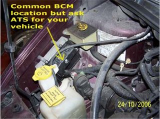
Get hold of the bcm wiring diagram from ATS. Using the bcm diagram, you can identify all the components that being controlled by the bcm by using the wiring colors associated with the part or component. A lot of times, the location of the component is described in the wiring diagram. BCM components usually include lights, power mirror, window and door locks, anti-theft, windshield wiper system, radio, instrument cluster, horn, all vehicle openings like trunks, defogger, power steering, AC, cruise control and other accessories.
The first test of the bcm is using a scanner. It will tell you right away which part of the bcm system is malfunction. It can also isolate the particular circuit in the bcm to narrow down your test. Remember: bcm code is not the same as the engine code.
To test the bcm, start by checking the ground pins for voltage which must not be higher than 0.250 volts. If it does, it means there is a short in the wires or one of the components. To verify, unplug the components one of the time until the voltage reading returns to normal.
Make sure all connections to the bcm and components are tight and not corroded.
The BUS plus and minus communication pins at the bcm can be checked and it should measure about 2.5 volts (ask ATS for the exact voltage for your vehicle) with key on. If none or higher voltage reading, it indicates an open wire or defective bcm or component. Again try to unplug the component one at a time to test.
ATS tips:When working with bcm, always read all the blog posts by searching the word "bcm" on the top left corner bar of this blog and click "search this blog" beside it.
BCM when replaced needs to be reprogrammed by the dealer when bought new. When buying one from the salvage yard, make sure it is the same match for your vehicle. Sometimes, the bcm does not include the alarm system and can cause future problems.


